Spark Transmitter -
Does it ring a bell? No? Let me ask it another way, have you ever
driven a gasoline powered vehicle? Or even listened to ignition noise
from one? What is that noise? It is the broad spectrum electromagnetic
wave propagation from a spark gap.
A modern car uses the exact components found in a 1900 Spark transmitter; a
battery, an induction coil to step up to high voltage (ignition coil), a
spark gap (spark plug) and an antenna (ignition wiring). All
that’s missing is a telegraph key. If we grounded the car’s chassis,
connected an antenna directly to the ignition coil’s HV output and added
a telegraph key in series with the ignition coil primary, we could
transmit Morse code to a range of about 10 miles using this set up.
A Spark Transmitter is a rudimentary communication system which was used as a telegraph.
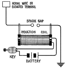
Basic operation
is straightforward. Close the key and the induction coil’s output rises
to a sufficient voltage to begin and then maintain an arc across the
spark gap. But how does this create an EM wave we can transmit?
The
spark gap itself is an electronic switch. When not firing, it is an
open circuit. When firing or “arcing over” the air within the gap is
ionized into a conducting plasma and the resistance across the gap drops
to around two ohms. Gaps require high voltage to begin firing, but
require current, not voltage, to maintain firing once started. Spark gap
induction coils used limiting mechanisms to continue to deliver small
amount of current to the gap, (a 2Ω near-short across their secondary)
without burning up. The structure of the ionized discharge across the
gap is highly erratic, with constant current fluctuations occurring
within plasma. These fluctuations occur rapidly, with a frequency
content that covers nearly the entire EM spectrum. In 1887 Heinrich
Hertz referred to a spark gap as an “oscillator.” Being connected
directly to the antenna, the broad spectrum current fluctuations at the
spark gap are radiated by the antenna.
However,
this was very inefficient as continuous firing of the gap caused the
power in the spark to be limited by the current the induction coil could
deliver into the 2Ω load of the gap–typically 100 mA or less resulting
in poor efficiency. Also,
emitted energy was spread over wide spectrum that receivers could hear,
effectively putting all users onto one shared channel. A ship’s radioman
would simply listen for a break in the traffic and then transmit. That
procedure limited interference, but it had shortcomings. On the night of
14 April 1912, the RMS Titanic
was so busy handling passengers’ ship-to-shore messages that it rebuffed
an attempted transmission from the nearby Californian trying to warn it
of icebergs in the vicinity and rest is history.

Addition of capacitor
was one of the major improvements introduced to Spark Transmitters.
When the telegraph key was depressed, it formed a complete circuit and
the electricity from the battery flew through resistor (Rc) into
capacitor (Cc). The capacitor charged until sufficient voltage was
achieved to fire the gap, at which point the gap fired, the capacitor
was discharged and the spark extinguished. This allowed the charge in
capacitor (Cc) to rush across the gap into capacitor (C). The coil (L)
and capacitor (C) along with the resistance (R) of the circuit make up a
resonator. The energy stored in the capacitor and delivered to the gap
was ½CV2. At 10,000 volts, voltage squared yields a lot of energy!
Also, development of the resonant tank circuit(L-C) early in the last century enabled a transmitter and receiver to communicate on just one specific frequency.
Spark
gap transmitters were the first type of radio transmitter to be widely
used. Later, more efficient transmitters were developed. However, most
operators still preferred spark transmitters because of their
uncomplicated design.
No comments:
Post a Comment